- 您现在的位置:买卖IC网 > Sheet目录1168 > 71M6533-DB (Maxim Integrated Products)BOARD DEMO 71M6533
�� �
�
�71M6533-� DB� Demo� Board� User’s� Manual�
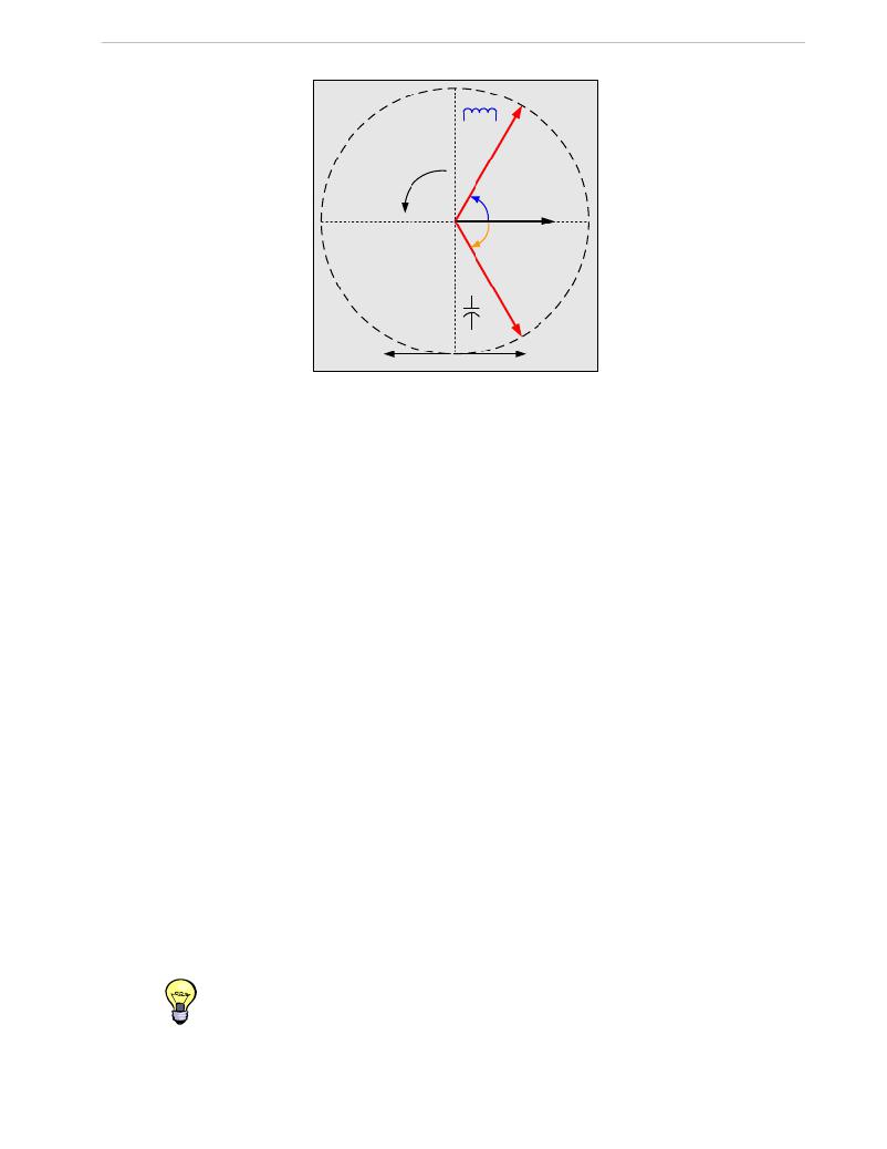
�Voltage�
�Current� lags�
�voltage�
�Positive�
�(inductive� )�
�direction�
�+60°�
�Current�
�-60°�
�Current� leads�
�voltage�
�(capacitive� )�
�Voltage�
�Generating� Energy�
�Using� Energy�
�Figure� 2-2:� Phase� Angle� Definitions�
�The� calibration� procedures� described� below� should� be� followed� after� interfacing� the� voltage� and� current� sensors�
�to� the� 71M6533� chip.� When� properly� interfaced,� the� V3P3� power� supply� is� connected� to� the� meter� neutral� and� is�
�the� DC� reference� for� each� input.� Each� voltage� and� current� waveform,� as� seen� by� the� 71M6533,� is� scaled� to� be�
�less� than� 250mV� (peak).�
�2.2.1� CALIBRATION� PROCEDURE� WITH� THREE� MEASUREMENTS�
�Each� phase� is� calibrated� individually.� The� calibration� procedure� is� as� follows:�
�1)�
�2)�
�3)�
�4)�
�5)�
�6)�
�7)�
�8)�
�9)�
�The� calibration� factors� for� all� phases� are� reset� to� their� default� values,� i.e.� CAL_In� =� CAL_Vn� =� 16384,�
�and� PHADJ_n� =� 0.�
�An� RMS� voltage� V� ideal� consistent� with� the� meter’s� nominal� voltage� is� applied,� and� the� RMS� reading�
�V� actual� of� the� meter� is� recorded.� The� voltage� reading� error� Axv� is� determined� as�
�Axv� =� (V� actual� -� V� ideal� )� /� V� ideal�
�Apply� the� nominal� load� current� at� phase� angles� 0°� and� 60°,� measure� the� Wh� energy� and� record� the�
�errors� E� 0� AND� E� 60� .�
�Calculate� the� new� calibration� factors� CAL_In� ,� CAL_Vn,� and� PHADJ_n� ,� using� the� formulae� presented�
�in� section� 2.1.1� or� using� the� spreadsheet� presented� in� section� 2.2.4.�
�Apply� the� new� calibration� factors� CAL_In� ,� CAL_Vn� ,� and� PHADJ_n� to� the� meter.� The� memory�
�locations� for� these� factors� are� given� in� section� 1.9.1.�
�Test� the� meter� at� nominal� current� and,� if� desired,� at� lower� and� higher� currents� and� various� phase�
�angles� to� confirm� the� desired� accuracy.�
�Store� the� new� calibration� factors� CAL_In� ,� CAL_Vn� ,� and� PHADJ_n� in� the� EEPROM� memory� of� the�
�meter.� If� the� calibration� is� performed� on� a� Maxim’s� Teridian� Demo� Board,� the� methods� involving� the�
�command� line� interface,� as� shown� in� sections� 1.9.3� and� 1.9.4,� can� be� used.�
�Repeat� the� steps� 1� through� 7� for� each� phase.�
�For� added� temperature� compensation,� read� the� value� TEMP_RAW� (CE� RAM)� and� write� it� to�
�TEMP_NOM� (CE� RAM).� If� Demo� Code� 4.6n� or� later� is� used,� this� will� automatically� calculate� the�
�correction� coefficients� PPMC� and� PPMC2� from� the� nominal� temperature� and� from� the� characterization�
�data� contained� in� the� on-chip� fuses.�
�Tip:� Step� 2� and� the� energy� measurement� at� 0°� of� step� 3� can� be� combined� into� one� step.�
�Page:� 39� of� 75�
�`�
�REV� 3�
�发布紧急采购,3分钟左右您将得到回复。
相关PDF资料
71M6534H-DB
BOARD DEMO 71M6534H
71M6541F-DB
DEMO BOARD 71M6541F
71M6543F-DB-CT
DEMO BOARD 71M6543F-DB-CT
72-CNV-5
CONVERTER RS-232 TO RS-422 5V
72346-001
72346-1-SCA-II REC
72347-001LF
CONN RECEPT SCA2 20POS VERT PCB
72436-001LF
80POS EXT HT. REC SCA-2
72442-201LF
CONN RECEPT SCA2 80POS VERT PCB
相关代理商/技术参数
71M6533G
制造商:MAXIM 制造商全称:Maxim Integrated Products 功能描述:Exceeds IEC 62053/ANSI C12.20 Standards
71M6533G-IGTR/F
功能描述:计量片上系统 - SoC AC Power Monitoring SoC-Programd RoHS:否 制造商:Maxim Integrated 核心:80515 MPU 处理器系列:71M6511 类型:Metering SoC 最大时钟频率:70 Hz 程序存储器大小:64 KB 数据 RAM 大小:7 KB 接口类型:UART 可编程输入/输出端数量:12 片上 ADC: 安装风格:SMD/SMT 封装 / 箱体:LQFP-64 封装:Reel
71M6533H
制造商:TERIDIAN 制造商全称:TERIDIAN 功能描述:Energy Meter IC
71M6533H-IEL
制造商:Maxim Integrated Products 功能描述:Metering Systems on a Chip - SoC Precision Energy Meter IC
71M6533H-IEL/F
制造商:Maxim Integrated Products 功能描述:Metering Systems on a Chip - SoC Precision Energy Meter IC
71M6533H-IELR
制造商:Maxim Integrated Products 功能描述:Metering Systems on a Chip - SoC Precision Energy Meter IC
71M6533H-IELR/F
制造商:Maxim Integrated Products 功能描述:Metering Systems on a Chip - SoC Precision Energy Meter IC
71M6533H-IGT/F
功能描述:计量片上系统 - SoC Precision Energy Meter IC RoHS:否 制造商:Maxim Integrated 核心:80515 MPU 处理器系列:71M6511 类型:Metering SoC 最大时钟频率:70 Hz 程序存储器大小:64 KB 数据 RAM 大小:7 KB 接口类型:UART 可编程输入/输出端数量:12 片上 ADC: 安装风格:SMD/SMT 封装 / 箱体:LQFP-64 封装:Reel